
ST7789 / GC9A01 / ST7735 Init Problems: Offset, SPI Mode and CS
These three controllers sit behind most small SPI colour displays, and most “my display shows garbage / a shifted image / nothing” threads trace back to the same handful of causes: the controller RAM is larger than the glass, the CS pin changes which SPI mode works, and inversion and colour order are per-panel settings that example code cannot know. None of them are faults - they are configuration, and they are all fixable in software.
Written by the Junxian applications engineering team. Figures quoted for “our models” are calculated from the 103 models on this site that carry a full parameter set, so they change when the catalogue changes.
Same controller, different panel: why example code half-works
An ST7789 addresses a 240x320 pixel RAM regardless of the glass in front of it. A 240x280 or 240x240 panel shows a window into that RAM, and where that window sits is a property of the module, not the controller. Example code written for one module compiles and runs on another - and produces an image shifted by exactly the offset difference, with a band of noise where the unwritten RAM shows. The fix is one line: set the column and row offsets for your module before drawing.
The offset numbers, and where to get them
For a 240x320 panel the offsets are zero. For shorter glass the window is placed by the module maker - commonly centred, so a 240x280 panel starts 20 rows in, and a 240x240 panel 80 rows in on one rotation - but “commonly” is not a specification. The authoritative numbers are in the module datasheet, and they can differ between two modules that look identical. If your image is shifted by a constant amount in one axis, you are looking at an offset problem, not a timing problem.
SPI mode, and the boards with no CS pin
These controllers sample SPI in mode 0 with CS driven normally. Some breakout boards tie CS permanently low to save a pin - and with CS never toggling, the controller loses the edge it uses to frame the transaction, which in practice means the module only works in SPI mode 3. So: board has a CS pin, use mode 0 and drive it; board has no CS pin, try mode 3 before concluding the module is dead. Mixing this up produces a perfectly white, perfectly silent screen.
Inverted colours and swapped red/blue
Whether the glass is normally-black or normally-white decides if the inversion command must be on or off - get it wrong and you see a photographic negative. Separately, the RGB/BGR bit decides channel order - get that wrong and reds and blues swap while everything else looks fine. Both are one-command fixes, both are per-panel properties, and both are the first thing to try when colours are wrong but geometry is right.
Reset and shared-bus discipline
All three controllers need a deliberate reset pulse and a wait before the init sequence, and a further wait after sleep-out - shortening these delays to speed boot is a false economy that produces intermittent cold-start failures. On a bus shared with SD cards or flash, every device needs its CS managed; a floating CS on any device can corrupt the display's transactions only sometimes, which is the worst kind of bug to chase.
Library configuration: where the settings live
Whether you use TFT_eSPI, LVGL with a driver layer, u8g2 for monochrome, or a vendor HAL, all of the above surface as configuration entries: driver selection, width, height, column offset, row offset, SPI mode, inversion, colour order. The library is rarely wrong; its defaults are simply for a different module. Copying a configuration from a forum post transplants that stranger's module onto yours - use the numbers from your module's datasheet instead.
The controllers we ship and what you get with them
The table below is the driver IC mix across our published models. For any of them, ask with the model number and we supply the verified initialisation table for that module and batch - offsets, inversion, colour order and reset timing included - so the settings above are numbers you copy in, not numbers you discover.
| Driver / controller IC | Models using it | Sizes | Example model |
|---|---|---|---|
| ST7735S | 6 | 0.96", 1.77", 3.5", 7" | JM-PT034 |
| ST7789 | 5 | 2.4", 3.2" | JM-PT090 |
| ST7567 | 4 | 3" | JM-L12806404 |
| ST7701S | 3 | 3", 4", 5" | JM-PT128-00 |
| CH1116 | 2 | 1.54" | JM-PO150 |
| LT8619B | 2 | 7" | JM-GD814 |
| NV3052CRGB | 2 | 3.4", 4.3" | JM-TFT043BI051 |
| SSD1306BZ | 2 | 0.49", 0.96" | JM-PO107 |
| ST7066U | 2 | - | JM2004A |
| ST7262 | 2 | 5" | JM-TFT050BI52 |
| ST7262E43 | 2 | 4.3" | JM-PT042 |
| ST7789P3 | 2 | 2.4" | JM-PT095-01 |
| T6963C | 2 | 1.3", 5.2" | JMP0121 |
| 9881 | 1 | 10.1" | JM-PT134-01 |
| ATP31066 | 1 | 3.2" | JM-2004C-00 |
| CST8922 | 1 | 7" | JM-PT121-01 |
| EK9713 | 1 | 7" | JM-PT098-00 |
| GC9107 | 1 | 1.77" | JM-PT077 |
| GC9503CV | 1 | 4.45" | JM-PT097 |
| GC9A01 | 1 | 1.28" | JM-PT106-00 |
| ILI 9340X | 1 | 3.5" | JM-PT075 |
| ILI 9341V | 1 | 2.4" | JM-GD819 |
| ILI9340X | 1 | 2.8" | JM-PT119-01 |
| ILI9488 | 1 | 3.5" | JM-PT048-01 |
| ILI9881C | 1 | 10.1" | JM-PT125-00 |
| KS0066U | 1 | - | JM2002A |
| LC7981 | 1 | - | JM240128J-1 |
| NT7108 | 1 | 4.3" | JM19264C |
| NV3047EGHK-H2 | 1 | 4.3" | JM-PT105-01 |
| RA6963C | 1 | - | JM24064A |
| RA8835 | 1 | 5.7" | JM320240A |
| SBN1661G | 1 | - | JM12232B |
| SH1106G | 1 | 1.3" | JM-PO139-01 |
| SPLC780D | 1 | - | JM1602M |
| SSD1306 | 1 | 1.3" | JM-PO158-01 |
| SSD1309 Or Equivalent | 1 | 2.42" | JM-P0159-00 |
| SSD1315Z | 1 | 0.96" | JM-PO136 |
| SSD1351 | 1 | 1.46" | JM-PO128 |
| ST7066 | 1 | - | JM0802B |
| ST7257 | 1 | 5" | JMT050WQ3TNN-01 |
| ST7265 | 1 | 5" | JM-PT136-00 |
| ST7272A | 1 | 3.5" | JM-PT113 |
| ST75160 | 1 | 2.5" | JM16096C02 |
| ST75161 | 1 | 3" | JM-PL054-00 |
| ST7525 | 1 | 2" | JM-PL042-LG19264 |
| ST75256 | 1 | 2.9" | JM240128C07 |
| ST7567R | 1 | 1.5" | JM-PL024 |
| ST7567S | 1 | 3.2" | JM-PL051-LG12864 |
| ST7735 | 1 | 1.77" | JM-PT130-00 |
| ST7735P3 | 1 | 0.96" | JM-PT138-00 |
| ST7789T3-G4-1 | 1 | 2.8" | JM-PT033-01 |
| ST7789V | 1 | 1.3" | JM-PT115-00 |
| ST7789V2 | 1 | 2" | JM-PT086 |
| ST7789V3 | 1 | 1.14" | JM-PT149-00 |
| ST7920 | 1 | 3.8" | JM12864G |
| UC1604c | 1 | 2" | JM19264C03 |
| UC1628C | 1 | 2.9" | JM240160C02 |
| UC1698U | 1 | 5" | JM240128C09-GSBLWNG5 |
| UI_Editor-II | 1 | 4.3" | JM-LH018-00 |
Taken from the published specification of each model. A further 21 published models do not name the controller on the public page - that is deliberate on glass where the source can change; ask and we will confirm the current IC for a specific order.
Published models on these controllers
Published models that illustrate the point above - full specifications on each page.
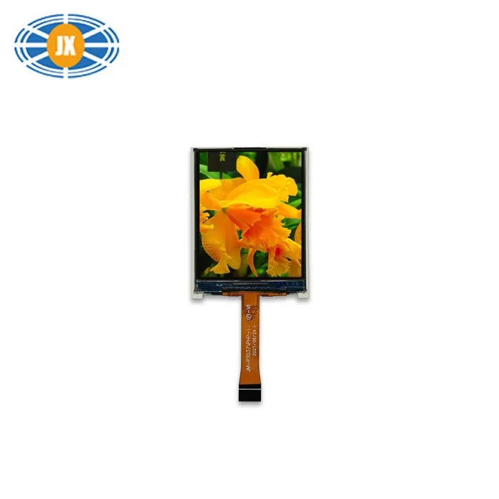
1.77 Inch TFT LCD Display 4 Bit 128×160 Pixels Color TFT Display SPI I
JM-PT037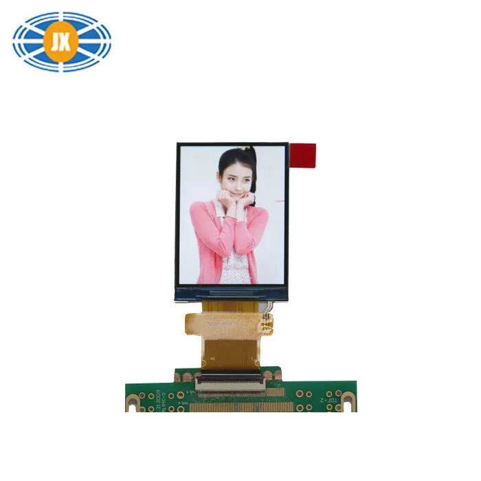
Custom 2.4 Inch TFT LCD Display 240×320 MCU Interface 350cd/m2 High Br
JM-PT090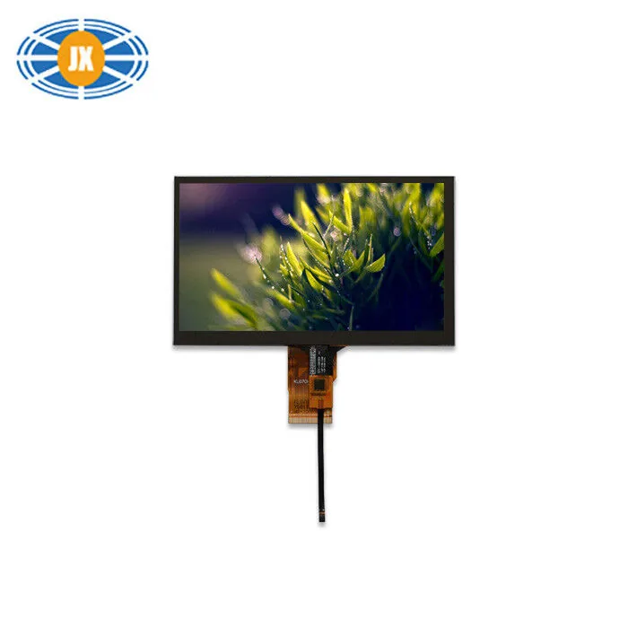
300cd/m2 High Brightness LCD Display 7 Inch 1024x600 For Automotive
JM-PT034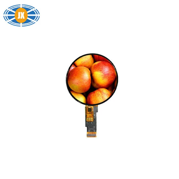
1.28 Inch Round TFT LCD Display Custom Touchscreen LCD Panel 240×240 P
JM-PT106-00Related guides
TFT Shows a White or Blank Screen: a Hardware Checklist
A white screen is usually good news: the backlight works and the panel is powered, but the driver IC never received a valid initia...
Driver ICs We Use, and Why the Controller Matters to Your Firmware
The driver IC is the part your firmware actually talks to. It sets the initialisation sequence, the command set, the addressing mo...
LCD Interfaces Explained: SPI, MCU, RGB, LVDS and MIPI
The interface is the first decision, not the last: it decides whether your processor can drive the panel at all, how many pins the...
Questions engineers ask us about this
My ST7789 240x280 image is shifted by 20 pixels. Why?
The controller RAM is 240x320 and your glass is a 240x280 window into it, placed 20 rows in. Set the row offset for your rotation and the image lands where it should. The equivalent on 240x240 glass is an 80-row offset on one rotation.
My GC9A01 round display stays white with wiring I know is right.
Check CS handling first: these controllers want mode 0 with a driven CS, or mode 3 on boards where CS is tied low. Then check the reset is a deliberate GPIO pulse with the datasheet wait, not a side effect of MCU reset. Those two cover most silent white screens on round modules.
Colours are inverted - is the module faulty?
Almost certainly not: the inversion setting in your init does not match the glass type. Toggle the inversion command and it will read correctly. If red and blue are swapped instead, toggle the RGB/BGR order bit.
Is ILI9341 the same as ST7735 / ST7789 for these problems?
The failure modes are the same family - offsets, SPI framing, inversion, colour order - the register values differ. The diagnostic method in this guide applies to any small SPI TFT controller, whichever IC is fitted.
Can you confirm which controller a module uses before I order?
Yes. Some of our published pages deliberately do not name the controller where the source can change; ask about a specific model and order quantity and we confirm the current IC and supply its init table. If controller continuity matters to your firmware, say so and it becomes part of the order terms.
Need a quote or a datasheet?
Send us size, resolution, interface and annual quantity. Our engineers reply within one working day. Sample MOQ 5 pcs, lead time 10-20 days.